| Scimitar 'A' post repair | |
|
| Repairing the "A" post might seem a bit worrying at first but once I had worked out how to do it, I found it was not too bad! | |
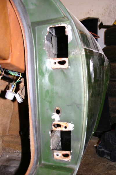
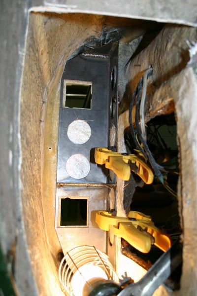
| To repair the 'A' Post I firstly cut into the inner wing. I have already removed all the suspension on my car so there was loads of room to get to the area. The inner wing is not part of the original molding and is added after with a strip of fibre glass around all sides. You should be able to see the strip of glass fibre. To cut the panel out I just used a Dremal tool and cut through the strip. Once you have removed the panel you can see the mess inside, you may find loads of leafs. At this stage maybe I should point out that you could remove the fan/blower unit from the foot well and using a mirror and a torch, you would be able to see inside the 'A' Post. Either way you have to remove the motor/blower panel to get into the 'A' Post. | |
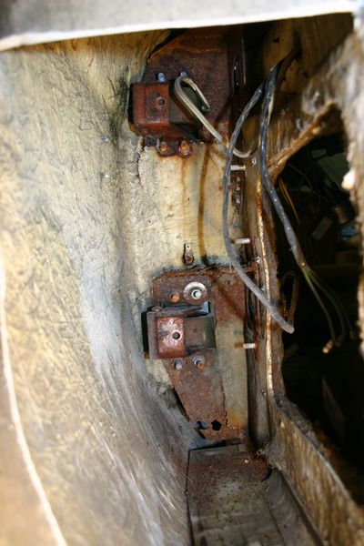
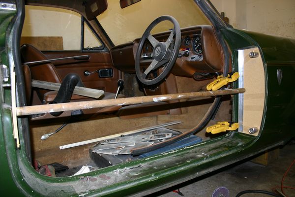
| Getting down to business. The door has been removed and fibre glass that was over the steel plate has been pulled off. You can see the amount of rust, this plate was rusty on both sides and had caused a lot of damage to the fibre glass behind it | |
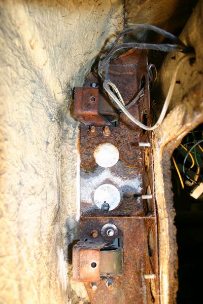
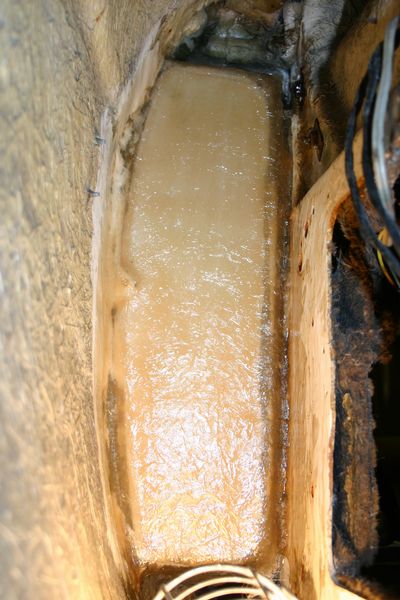
| This picture isn't very good (the camera struggled to focus) but you can see the patterns in the surface coinciding where the holes are in the steel plate. Also at the top on the 'A' Post where the top hinge is mounted you can see an area of fibre glass which has fallen off. In some places the fibre glass was only 1mm thick! | |
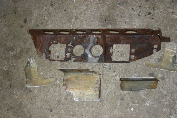
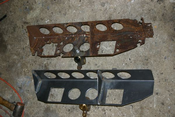
| I don't believe you can get a genuine repair panel for the 'A' Post, so I went to my friendly local fabrication shop and made one myself! I get on very well with the fab' shop owner and he basically just lets me cut my own metal and bend it! And on that particular day I made this panel, the sill reinforcement panel and the other small panel for the 'A' Post. The cost of these 3 panels???? Six pounds! | |
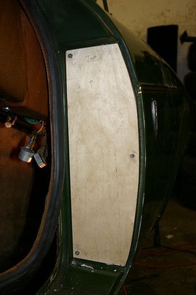
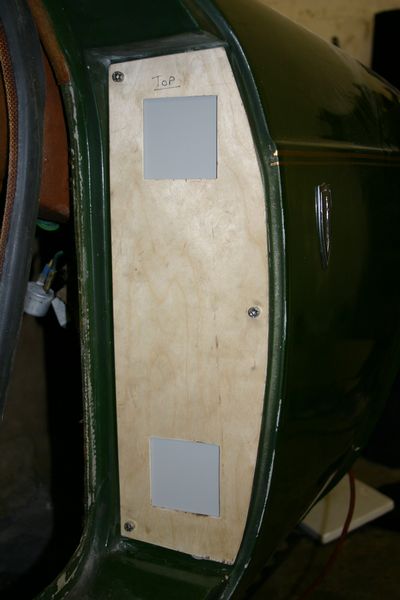
| This next step was very important. What looks like a boring piece of wood is actually my template! I have cut a piece of 1.5 mm ply to the correct shape and then drilled and screwed it to the 'A' Post using 3 screws. One is in the top left, one in the middle right and the other is at the bottom left. These were all drilled in an area out of the way (missing the steel reinforcement panel) and where the fibre glass was still ok. | |
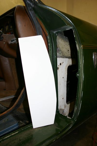
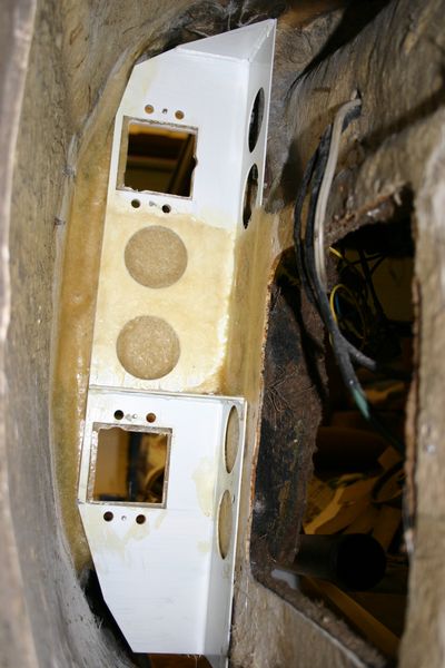
| Once I was happy with the template I attacked the 'A' Post again with my Dremel tool. This time I cut out all the old fibre glass leaving a big hole. At this point there is no turning back! | |
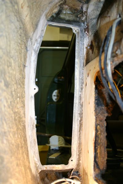
| This picture just shows the other side of the above picture. You can just make out the 3 holes where the template will be mounted again. Also to help the new fibre glass bond to the old I have cleaned back the fibre glass using a fibre wheel. And the edges have been chamfered to make a strong repair. | |
| Now the fun starts! | |
| OK , if you can't fibre glass maybe you really shouldn't have started this! It's not hard to do, but if you don't know what you are doing it is very easy to get it wrong. I worked alongside a laminator at a fibre glass shop for a week and I learnt the basics of glass fibre. | |
| I allowed the resin to harden overnight and then the next morning removed the brace and tape and carefully pulled off the hard board (The wax made removal very easy). The gel coat was done in grey for no other reason than, it was all that the local fibreglass company had! If you have to buy your fibre glass from suppliers, then you could end up paying a lot for resin and CSM, but because I get mine from a local laminator he sells it to me at cost plus beer money. | |
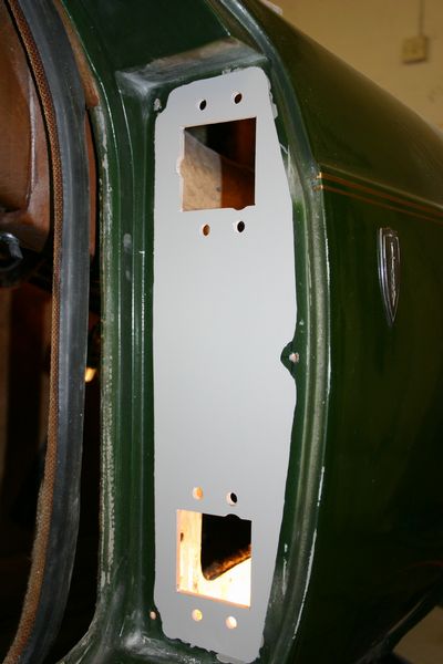
| I was really happy with how this repair was going and so I took my time with the next few stages to get it all right. In this picture you can see the template has been screwed back on to the "A" Post. The holes had to be drilled through again as the fibre had been laid over the back of them. The template has had the square hinge holes cut out but as yet I haven't drilled the retaining holes. | |
| Now it's really starting to look good! All the holes are drilled. To make this step easier I took the hinges off the door and held them up to the square holes and marked through the bolt holes so they matched up. | |
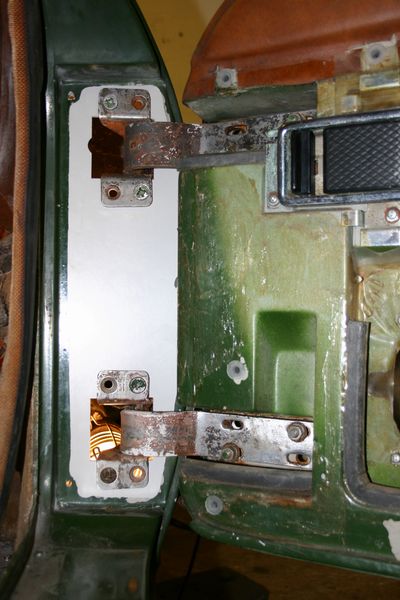
| Just for a last minute check on the alignment I have bolted the door back on to check the fit. At the moment the steel reinforcement panel hasn't been fibre glassed in. Even without the reinforcement panel, the "A" Post is very ridged and the door felt very solid. The hinges have loads of adjustment on them and in the case of my door the hinges had a shim behind them made out sanding paper! | |
| The steel plate needs to be fibre glassed into place on two sides, the "A" Post and the foot well. So I offered it up and using pieces of dry CSM spaced it out so I could mark out and drill the holes for the hinges and for the other plate which fixes to the foot well via 3 bolts. | |
| To get everything lined up whilst fibre glassing the panel into place, I decided to drill and tap 4 small countersunk screws through the "A" Post. This will allow me to glass the panel into place and then pull it tightly to the "A" Post and get a really good strong bond. As you can see in the picture the screws have been drilled in between the two main fixing bolts and as explained they are countersunk such that the hinge will sit flat over them and you won't know they are there. The screws are stainless steel so won't rust. | |
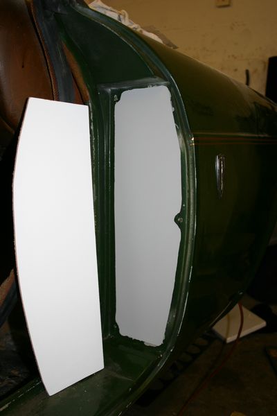
This is the finished repair. The panel was held in place with one layer of CSM, which was laid up really wet, then as the panel was put into place and then screwed up using the countersunk screws the excess resin was squeezed out and hopefully any bubbles would have also been excluded. The panel which was made out of steel has been etch primed using a zinc rich etch primer. This will offer good protection against the water and also acts as a really good adhesion promoter between the fibre glass and steel. |
| If you would like a link adding or any details on the website then please email me |